- 您现在的位置:买卖IC网 > Sheet目录221 > DS1904L-F5# (Maxim Integrated)IBUTTON RTC F5 MICROCAN
�� �
�
 �
�DS1904�
�READ� CLOCK� [66h]�
�The� read� clock� command� is� used� to� read� the� device� control� byte� and� the� contents� of� the� real-time� clock�
�counter.� After� having� received� the� most� significant� bit� of� the� command� code� the� device� copies� the� actual�
�contents� of� the� real-time� clock� counter� to� the� read/write� buffer.� Now� the� bus� master� reads� data� beginning�
�with� the� device� control� byte� followed� by� the� least� significant� byte� through� the� most� significant� byte� of� the�
�real-time� clock.� After� this� the� bus� master� may� continue� reading� from� the� DS1904.� The� data� received� will�
�be� the� same� as� in� the� first� pass� through� the� command� flow.� The� read� clock� command� can� be� ended� at� any�
�point� by� issuing� a� Reset� Pulse.�
�WRITE� CLOCK� [99h]�
�The� write� clock� command� is� used� to� set� the� real-time� clock� counter� and� to� write� the� device� control� byte.�
�After� issuing� the� command,� the� bus� master� writes� first� the� device� control� byte,� which� becomes� immedi-�
�ately� effective.� After� this� the� bus� master� sends� the� least� significant� byte� through� the� most� significant� byte�
�to� be� written� to� the� real-time� clock� counter.� The� new� time� data� is� copied� from� the� read/write� buffer� to� the�
�real-time� clock� counter� and� becomes� effective� as� the� bus� master� generates� a� reset� pulse.� If� the� oscillator� is�
�intentionally� stopped,� the� real-time� clock� counter� behaves� as� a� four-byte� non-volatile� memory.�
�1-WIRE� BUS� SYSTEM�
�The� 1-Wire� bus� is� a� system,� which� has� a� single� bus� master� and� one� or� more� slaves.� In� all� instances� the�
�DS1904� is� a� slave� device.� The� bus� master� is� typically� a� microcontroller.� The� discussion� of� this� bus� system�
�is� broken� down� into� three� topics:� hardware� configuration,� transaction� sequence,� and� 1-Wire� signaling�
�(signal� types� and� timing).� A� 1-Wire� protocol� defines� bus� transactions� in� terms� of� the� bus� state� during�
�specified� time� slots� that� are� initiated� on� the� falling� edge� of� sync� pulses� from� the� bus� master.� For� a� more�
�detailed� protocol� description,� refer� to� Chapter� 4� of� the� Book� of� iButton?� Standards� .�
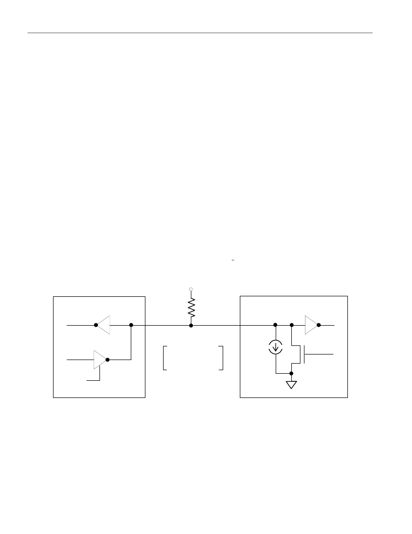
�HARDWARE� CONFIGURATION� Figure� 6�
�BUS� MASTER�
�Open� Drain�
�VPUP�
�5� k� ?�
�DS1904� 1-WIRE� PORT�
�RX�
�TX�
�Port� Pin�
�Typ.�
�RX� =� RECEIVE�
�TX� =� TRANSMIT�
�5� μA�
�Typ.�
�DATA�
�RX�
�TX�
�100� ?�
�MOSFET�
�Hardware� Configuration�
�The� 1-Wire� bus� has� only� a� single� line� by� definition;� it� is� important� that� each� device� on� the� bus� be� able� to�
�drive� it� at� the� appropriate� time.� To� facilitate� this,� each� device� attached� to� the� 1-Wire� bus� must� have� open�
�drain� or� three-state� outputs.� The� 1-Wire� input� of� the� DS1904� is� open� drain� with� an� internal� circuit�
�equivalent� to� that� shown� in� Figure� 6.� A� multidrop� bus� consists� of� a� 1-Wire� bus� with� multiple� slaves�
�attached.� The� 1-Wire� bus� has� a� maximum� data� rate� of� 16.3k� bits� per� second� and� requires� a� pull-up� resistor�
�of� approximately� 5k� ?� .�
�6� of� 13�
�发布紧急采购,3分钟左右您将得到回复。
相关PDF资料
DS1920-F5+
IBUTTON TEMPERATURE F5
DS1921G-F5#
IBUTTON THERMOCHRON F5
DS1921H-F5#
IBUTTON THERMOCHRON F5
DS1921K#
KIT IBUTTON THERMOCHRON
DS1922E-F5#
IBUTTON TEMP LOGGER 4KBit F5
DS1922L-F5#
IBUTTON TEMP LOGGER
DS1923-F5#
IBUTTON TEMP/HUMIDITY LOGGER F5
DS1961S-F3#
IBUTTON EEPROM 1KBit F3
相关代理商/技术参数
DS1904L-F5+
功能描述:iButton RoHS:否 存储类型:SRAM 存储容量:512 B 组织: 工作电源电压:3 V to 5.25 V 接口类型:1-Wire 最大工作温度:+ 85 C 尺寸:17.35 mm x 5.89 mm 封装 / 箱体:F5 MicroCan 制造商:Maxim Integrated
DS1920
制造商:DALLAS 制造商全称:Dallas Semiconductor 功能描述:Temperature iButton
DS1920+F5
制造商:Maxim Integrated Products 功能描述:TEMP IBTN 2PIN F5 MICROCAN - Rail/Tube
DS1920-F3
制造商:DALLAS 制造商全称:Dallas Semiconductor 功能描述:Temperature iButton
DS1920-F5
功能描述:iButton RoHS:否 存储类型:SRAM 存储容量:512 B 组织: 工作电源电压:3 V to 5.25 V 接口类型:1-Wire 最大工作温度:+ 85 C 尺寸:17.35 mm x 5.89 mm 封装 / 箱体:F5 MicroCan 制造商:Maxim Integrated
DS1920-F5+
功能描述:iButton Temperature iButton RoHS:否 存储类型:SRAM 存储容量:512 B 组织: 工作电源电压:3 V to 5.25 V 接口类型:1-Wire 最大工作温度:+ 85 C 尺寸:17.35 mm x 5.89 mm 封装 / 箱体:F5 MicroCan 制造商:Maxim Integrated
DS1921
制造商:DALLAS 制造商全称:Dallas Semiconductor 功能描述:High-Resolution Thermochron iButton
DS1921G
制造商:未知厂家 制造商全称:未知厂家 功能描述:Thermochron iButton